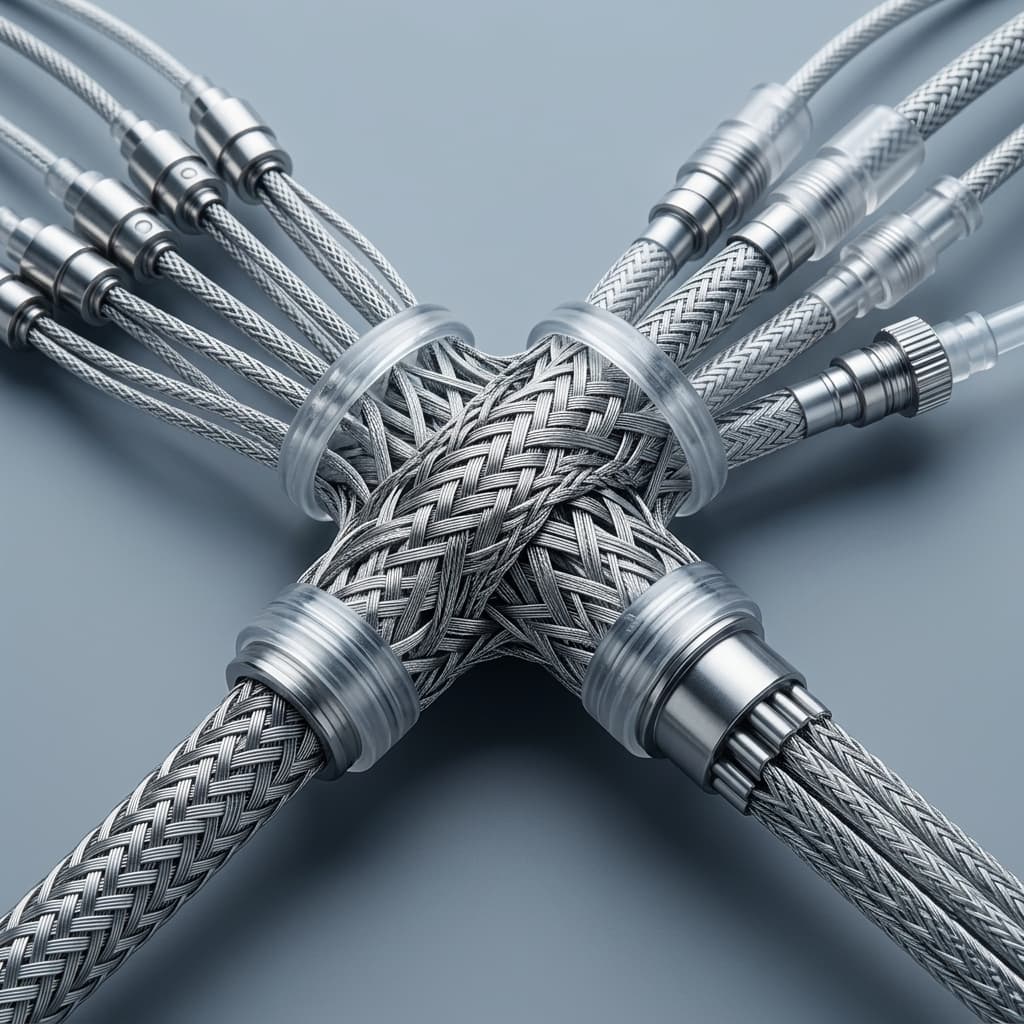
Round Wire vs. Flat Wire Braiding: Minimizing Catheter Wall Thickness Without Sacrificing Torque
Compare round wire vs flat wire catheter braiding for wall thickness, torque testing, manufacturing risks, and sourcing. Use the checklist to request a DFM review.
Round wire vs. flat wire catheter braiding is a wall-budget decision that also requires mechanical verification. Flat ribbon can reduce the radial height of a braid crossover when its thickness is smaller than the round-wire diameter. Neither shape alone guarantees 1:1 torque response, kink resistance, or vacuum-collapse performance.
For catheter R&D engineers and procurement teams, the useful comparison is the finished shaft: liner, braid geometry, alloy and temper, polymer jacket, interfaces, and manufacturing process. Wire shape also changes payoff control, inspection needs, and the assumptions behind a supplier quotation.
Selection rule: screen flat wire when the round-wire crossover exceeds your available wall budget; retain round wire as a candidate when it fits and its processing is established. Select between them using paired prototype measurements and a quote with explicit material and process assumptions.
This guide provides a reproducible wall calculation, a comparison matrix, manufacturing risk controls, and drawing specifications for an OEM RFQ.
Published and reviewed October 25, 2026. Scope: English-language engineering and sourcing guidance for global OEM teams comparing stainless steel or Nitinol catheter shaft braids. Dimensions below are illustrative design inputs, not commercial benchmarks or measured production results. The model assumes two undeformed strands crossing with flat ribbon lying face-down; it excludes compaction, dimensional tolerances, and reflow variation. No patient-outcome, regulatory-approval, price, yield, or lead-time claim is established here. Confirm the applicable standards and finished-device verification requirements for your intended market.
If you are currently drafting engineering prints or sourcing reinforcement layers, review our catheter shaft RFQ checklist or submit your specifications directly through the contact and RFQ portal for a DFM evaluation.
1. The Physics of Crossover Thickness: Where Profile Is Lost or Won
The total wall thickness of a laminated catheter shaft is governed by three sequential layers:
- The Inner Lubricious Liner: For example, PTFE, FEP, or high-density polyethylene (HDPE), with material and wall thickness specified on the drawing.
- The Reinforcement Layer: The metallic braid or coil matrix.
- The Outer Polymer Jacket: Extruded multi-durometer Pebax, nylon (PA12), or polyurethane (TPU), which melts and flows through the braid during thermal reflow lamination under FEP heat shrink tubing.
In a braided catheter, wire strands continuously cross over and under each other in a diamond (1-over-1) or regular (2-over-2) pattern. The critical architectural bottleneck is the crossover stack height—the point where two opposing wire strands intersect.
Round Wire Crossover Mechanics
For round wire with diameter d, the idealized crossover stack is 2 × d.
With d = 0.002" (50.8 µm), the stack is 0.004" (101.6 µm). Add an assumed 0.001" liner and 0.0018" polymer cap above the crossover: the calculated single-side wall is 0.0068" (172.7 µm). These cap and liner dimensions are example inputs, not minimum manufacturing requirements. Twice that wall, 0.0136", is the total OD-minus-ID allowance; it includes all three layers, not just reinforcement.
Flat Wire (Ribbon) Crossover Mechanics
Flat ribbon is specified as thickness T × width W. When both ribbons lie flat, the idealized stack is 2 × T. For 0.0007" × 0.003" ribbon, this gives 0.0014" (35.6 µm).
Keep the liner and cap identical to isolate the effect of wire thickness:
| Model input or result | Round wire example | Flat ribbon example |
|---|---|---|
| Wire cross-section | Diameter 0.002" | Thickness 0.0007" × width 0.003" |
| Inner liner wall | 0.001" | 0.001" |
| Two-strand crossover | 0.004" | 0.0014" |
| Polymer cap above crossover | 0.0018" | 0.0018" |
| Calculated single-side wall | 0.0068" (172.7 µm) | 0.0042" (106.7 µm) |
| Total OD-minus-ID allowance | 0.0136" | 0.0084" |
Calculated ID at an assumed 0.080" OD | 0.0664" | 0.0716" |
| Metal area per strand, ignoring ribbon edge rounding | 0.00000314 in² | 0.00000210 in² |
Reproduce the calculation: wall = liner + crossover + cap; ID = OD − 2 × wall; 1 inch = 25.4 mm. The round area is π × d² / 4; the approximate ribbon area is T × W. The example ribbon has about one-third less metal area, so this is a geometric screening comparison, not a mechanically matched substitution.
The Engineering and Sourcing Payoff
In this example, the difference is 0.0026" (66.0 µm) per side, or 0.0052" (0.132 mm) across the diameter. Since 1 Fr = 1/3 mm of OD, that is approximately 0.40 Fr; it does not establish a reduction from 6 Fr to 5 Fr.
At fixed OD, this allowance could increase ID; at fixed ID, it could reduce OD. Actual savings depend on tolerances, encapsulation, and reflow. Neither the calculation nor a larger nominal lumen establishes aspiration flow, clinical benefit, or unchanged torque performance.
2. Mechanical Performance Comparison: Torque, Kink, and Column Strength
Torque Transmission and Response
A circular wire has the same cross-sectional bending geometry about any transverse axis; a rectangular ribbon has different bending stiffness about its thin and wide axes. These strand properties do not, by themselves, rank finished catheter torque performance. Braid angle, carrier count, coverage, alloy, jacket stiffness, bonding, shaft length, and friction all matter.
Neither round nor flat wire guarantees 1:1 rotational tracking. Increasing picks per inch (PPI) also changes coverage and flexibility, so it is not a universal cure for torque lag. Record the PPI counting convention and braid angle relative to the shaft axis before comparing suppliers.
Kink Resistance and Vacuum Collapse
A wider ribbon changes coverage and the way radial loads enter the braid. It can be a useful candidate for a constrained wall, but collapse resistance depends on the entire construction. Thin ribbons can also twist or develop local creases. Neither shape ensures a circular lumen during bending or aspiration.
A Paired Prototype Comparison Before Approval
- Define two comparisons: equal finished OD/ID for product selection, and a controlled braid comparison for understanding wire effects. State which variables are held constant and which must change.
- Record wire dimensions and tolerances, alloy/temper, strand count, PPI convention, braid angle, liner, jacket zones, reflow conditions, and usable shaft length for each build.
- Measure final OD/ID, ovality, and cross-sectional wall at multiple axial and circumferential locations, including crossover regions. Record sample count, measurement resolution, and lot identity.
- In the same fixture and defined fluid/temperature conditions, measure proximal input angle against distal output angle under a specified distal load. Record lag, hysteresis, torque versus angle, and any sudden release during rotation in both directions.
- Compare bend radius at a defined lumen-loss criterion and pressure/vacuum behavior in the intended curved geometry. Define pressure reference, duration, conditioning, and acceptance limits before testing; repeat after the intended sterilization and aging conditions where applicable.
This is a proposed evaluation method, not a report of tests performed by Catheterbraidingoem. Only the measured results can establish whether a thinner construction retains your required torque and lumen performance.
3. Structural Comparison Matrix
Use this matrix to identify RFQ questions. The dimensions in section 1 are example inputs; the table does not establish universal wall minima or performance rankings.
| Performance / Sourcing Metric | Round Wire Braid Architecture | Flat Ribbon Wire Architecture | Engineering & Sourcing Impact |
|---|---|---|---|
| Wire dimensions | Specify diameter and tolerance | Specify thickness, width, and both tolerances | Request measured wire data for the proposed lot |
| Ideal crossover height | 2 × d | 2 × T, when lying flat | Evaluate worst-case dimensions and actual compaction |
| Metal area per strand | π × d² / 4 | Approximately T × W, less edge rounding | Equal profile does not imply equal metal area or strength |
| Finished wall | Liner + crossover + polymer cap in the screening model | Same model, with ribbon orientation controlled | Confirm actual wall sections after reflow |
| Torque response | Depends on complete braid and jacket construction | Depends on complete braid and jacket construction | Compare input/output rotation under the same load |
| Hoop support / ovalization | Depends on coverage, angle, and interfaces | Wider strand face changes coverage and load distribution | Test lumen retention in the intended bend and vacuum conditions |
| Kink behavior | Depends on alloy, temper, and shaft construction | Also sensitive to ribbon orientation and local creasing | Use a defined bend-radius and lumen-loss criterion |
| Jacket surface | Crossovers can telegraph through insufficient encapsulation | Thin flat crossovers may help; twisted ribbon can protrude | Set surface and encapsulation acceptance criteria |
| Payoff control | Rotation does not change circular cross-section height | Ribbon rotation changes radial envelope | Check bobbin winding, guides, and tension stability |
| Cost | Quote against the specified alloy, dimensions, and quantity | Include rolling, edge finishing, setup, and inspection | Compare cost per accepted shaft, including NRE |
| Lead time | Depends on qualified inventory and processing | Depends on qualified inventory, rolling, and finishing | Obtain dated written commitments for each option |
4. Manufacturing Realities and Quality Risk Controls
For sourcing managers and manufacturing engineers, flat wire evaluation should include bobbin winding, carrier payoff, edge condition, and thermal lamination. Steeger USA's medical braider documentation describes round- and flat-wire capability and a carrier design intended to limit twisting and tension peaks. This supports evaluating the payoff system; it does not establish a universal tension setting or a particular supplier's capability.
Ribbon Twist
For the example 0.0007" × 0.0030" ribbon, an idealized 90-degree rotation changes the radial dimension from thickness to width. If two ribbons are both edge-on at a crossover, their combined envelope could approach 0.0060" instead of 0.0014". A 180-degree rotation returns the same face-down cross-sectional height, although the intervening twist can still create a local defect.
The resulting local protrusion can affect OD, encapsulation, or the liner. Inspect ribbon orientation at the braid point and the laminated shaft, and use OD mapping or cross-sections as appropriate. An OD gauge alone does not prove liner integrity. Qualify tension and guide settings for the actual alloy, ribbon dimensions, mandrel, and line speed rather than adopting a generic grams-of-tension limit.
Edge Condition and Liner Damage
Burrs or unsuitable ribbon edges can score a thin liner during braiding. Specify the edge profile, burr limit, surface condition, and inspection method with the wire supplier. If a rounded profile is required, define its geometry and acceptance range on the drawing. A maximum radius alone does not exclude sharp edges.
ASTM A313/A313M and ASTM F2063 are material references, not evidence that a particular ribbon edge radius prevents liner damage. Confirm applicability to the supplied product form and revision, then assess liner integrity on the finished construction.
Aspect Ratio and Winding
Aspect ratio is W / T; the example 0.0030 / 0.0007 is approximately 4.3:1. Higher aspect ratio changes bending and winding behavior, but this guide establishes no universal optimal ratio, rejection threshold, or scrap percentage. Ask for evidence that the proposed wire can be wound and braided without unacceptable twist, camber, edge damage, or dimensional variation.
5. Sourcing & Cost Economics: Evaluating the Total Cost of Ownership
A wire-shape choice does not establish a fixed unit-price premium or delivery window. Obtain like-for-like quotations with the same alloy, finished dimensions, acceptance criteria, lot size, and delivery basis.
| Cost Driver | Round Wire RFQ Question | Flat Ribbon Wire RFQ Question | Sourcing Mitigation Strategy |
|---|---|---|---|
| Raw material | Is the exact diameter and temper qualified and available? | Are thickness, width, and edge finish available or custom? | Confirm material certificate, MOQ, and usable stock |
| Spooling | Which bobbin format is included? | How is ribbon orientation controlled during winding? | Agree the winding and payoff format before ordering |
| Setup / NRE | Which tooling and setup are included? | Are guide changes or winding trials additional? | Separate one-time charges from recurring price |
| Production rate | What rate was demonstrated for this construction? | What rate maintains orientation and dimensional quality? | Request lot-specific assumptions rather than machine maximum speed |
| Yield / inspection | How are startup loss and inspection charged? | How are twist, burr, and liner defects detected and costed? | Compare cost per accepted shaft and document rejection rules |
| Reflow tooling | What cap thickness and shrink process are proposed? | Has encapsulation been demonstrated with this ribbon? | Qualify the full laminated stack |
| Delivery | What qualified stock is reserved? | Are rolling, finishing, or qualification steps on the critical path? | Obtain a dated schedule covering wire, prototypes, and release |
For an accepted-shaft comparison, ask the supplier to separate material, conversion, inspection, and allocated setup costs, and explain how yield enters its quote. Avoid dividing by yield again if the price already includes scrap. Neither low raw-wire price nor a nominally faster braiding cycle establishes lower total cost.
Bring the wall model, quantity, drawing revision, and required test evidence to a contact and RFQ review so both wire options can be quoted against the same requirements.
6. Application Archetypes: When to Evaluate Round vs. Flat Wire
These are starting points for prototype planning, not approved device architectures.
Neurovascular Microcatheters
When ID and OD leave little wall allowance, screen a thin flat ribbon against a sufficiently fine round wire. Compare distal bending, liner integrity, and torque lag after reflow; flat wire is not the only possible construction.
Aspiration Catheters
Evaluate braid or braid-coil candidates against the required vacuum and curved-path lumen retention. Specify a measurable ovalization or lumen-loss limit. Wire shape alone cannot establish collapse resistance or aspiration performance.
Guiding Catheters
If round wire fits the wall budget and its process is established, retain it as a baseline. Compare a flat-wire alternative when its profile benefit justifies qualification work. Verify torque lag and sudden release under the intended load rather than assuming immediate 1:1 response.
Steerable or Deflectable Sheaths
Include pull-wire lumens, compression under actuation, and local transitions in the wall model. Flat ribbon or layered reinforcement may be candidates, but additional layers and joints also consume profile and require verification.
7. DFM & RFQ Drawing Checklist for Procurement & Engineering
Use this checklist to replace vague callouts such as "braided with medical-grade wire." Values and acceptance limits must come from your design requirements and supplier feasibility review.
Wire Geometry & Metallurgy
- Cross-section: Specify round or flat ribbon; give diameter or thickness × width, units, tolerances, and measurement method.
- Edge and surface: Define ribbon edge profile, burr limits, surface finish, and inspection criteria; do not use a radius callout as a substitute for liner-integrity assessment.
- Material and condition: State alloy, temper, mechanical-property requirements, applicable material specification/revision, and lot traceability. Specify Nitinol transformation-temperature requirements and test method where relevant.
- Supply form: Confirm bobbin dimensions, winding direction, ribbon orientation, usable length, and splice policy.
Braid Pattern & Process Definition
- Carrier and strand count: State carrier count and ends per carrier separately.
- Pattern: Define the intended over/under sequence and termination method.
- PPI and angle: Give counting convention, target and tolerance, braid-angle reference, and any transition-zone locations.
- Coverage and payoff: Agree coverage requirements and inspection method; have the supplier propose a qualified tension and guide setup.
Finished Shaft & Acceptance Evidence
- Layer stack: Define lumen ID, liner wall, jacket materials/durometer zones, usable length, and final OD/ID tolerances. Distinguish mandrel dimensions from finished-lumen dimensions.
- Encapsulation and surface: Specify allowable telegraphing, exposed wire, liner damage, delamination, and inspection sampling/method.
- Mechanical acceptance: Define torque load and lag limits, bend fixture and lumen-loss criterion, and pressure/vacuum conditions with duration and reference pressure.
- Conditioning and records: Define sterilization/aging conditions where applicable, sample count, measurement capability, lot records, and required reports.
- Commercial basis: Separate NRE, MOQ, accepted quantity, material availability, qualification work, and committed delivery dates.
8. Frequently Asked Questions (FAQ)
Does flat wire always make a thinner catheter wall?
No. In the idealized crossover model, it reduces stack height only when ribbon thickness is smaller than the round-wire diameter being compared. Liner, cap, tolerances, ribbon twist, and reflow can change the finished result. The section 1 example saves 0.0052" across the diameter with identical liner and cap assumptions; this is not a production guarantee.
Can flat wire preserve the torque response of round wire?
It may meet the same requirement in a suitably designed shaft, but wire shape alone cannot establish equivalence. Compare finished shafts of defined geometry in the same loaded rotation fixture and record lag, hysteresis, and sudden release. The example wires have different metal areas and are not mechanically matched.
Can we mix round wire and flat wire in one shaft?
Hybrid constructions can be evaluated, including separate reinforcement zones or layers. Define how each transition or termination is made and test local wall, bond integrity, flex behavior, and torque continuity. Do not assume a wire change can be made seamlessly on a continuous braid.
Does flat wire reduce reflow cycle time?
A lower crossover changes the encapsulation geometry, but it does not establish a shorter thermal cycle. Polymer melt behavior, wall stack, tooling, shrink recovery, temperature history, and liner integrity determine the qualified process. Verify the cycle on the actual construction.
Does flat wire work on a standard 16- or 24-carrier braider?
Carrier count alone is insufficient. Confirm the machine's wire-size range, bobbin winding, guides, payoff behavior, and ability to maintain ribbon orientation. Request a trial with the intended ribbon and mandrel rather than assuming that a round-wire setup is suitable.
Is Nitinol flat wire available from stock?
Availability depends on dimensions, condition, finishing, and qualification requirements. Obtain a written stock confirmation or a schedule for the exact specification. This guide provides no universal Nitinol or stainless steel lead-time estimate.
9. Choosing the Right Path for Your Catheter Program
Choose prototype candidates in this order: calculate the wall allowance, check wire/process feasibility, compare finished-shaft mechanical results, then compare cost per accepted shaft and committed delivery dates. Flat ribbon is worth evaluating when its lower crossover resolves a real wall constraint; round wire remains a candidate when it fits and meets the required performance.
Request a DFM Review
Send Catheterbraidingoem your OD/ID targets, usable length, wire candidates, liner/jacket stack, quantities, and mechanical acceptance criteria through the contact and RFQ form. Ask the review to identify unresolved wall, payoff, encapsulation, and test requirements before prototype release.
For related design variables, see our variable pitch vs. multi-segment braiding guide and Nitinol vs. stainless steel wire analysis. Use those alongside construction-specific evidence when preparing your RFQ.
Sources & Industry References
These sources provide material-scope and equipment context. They do not substantiate universal torque rankings, cost premiums, scrap rates, lead times, or the calculated wall example. The cited 2018 ASTM editions are reference editions; confirm the applicable revision and product-form coverage in your controlled specification.
- ASTM International — ASTM F2063-18: Standard Specification for Wrought Nickel-Titanium Shape Memory Alloys for Medical Devices and Surgical Implants. Material-scope reference, not a finished braid or catheter performance specification. Automated access returned HTTP 403 during this review; the full standard was not examined.
- ASTM International — ASTM A313/A313M-18: Standard Specification for Stainless Steel Spring Wire. Stainless steel spring-wire reference; confirm applicability and any supplementary requirements for the proposed ribbon. Automated access returned HTTP 403 during this review; no standard-mandated edge radius is asserted.
- Steeger USA — Medical Braiders. Manufacturer documentation for medical braiding applications, carrier/payoff design, and material-dependent round- and flat-wire size capability. Equipment capability is not evidence of Catheterbraidingoem's installed equipment or validated shaft performance.
Author

More Posts
FDA Class I Recall (July 2026): Mitigating Distal Tip Detachment in Delivery Catheters
The recent Class I recall of a major delivery catheter system over distal tip detachment highlights critical risks in inner shaft assembly and transition zone bonding. Learn how buyers and OEM engineers can audit suppliers to prevent this manufacturing defect.

Catheter Marker Band Assembly: Swaging vs. Bonding for Radiopacity
A practical engineering guide to integrating radiopaque marker bands into reinforced catheter shafts. We compare swaging and thermal bonding techniques, dimensional tolerances, and inspection criteria.
ECHA PFAS Restriction Update (May 2026): Impact on PTFE Catheter Liners and OEM Procurement
A deep dive into the ECHA RAC and SEAC 2026 milestones regarding the EU PFAS restriction, and how medical device OEMs must navigate supply chain risks, derogations, and alternative materials like UHMWPE.