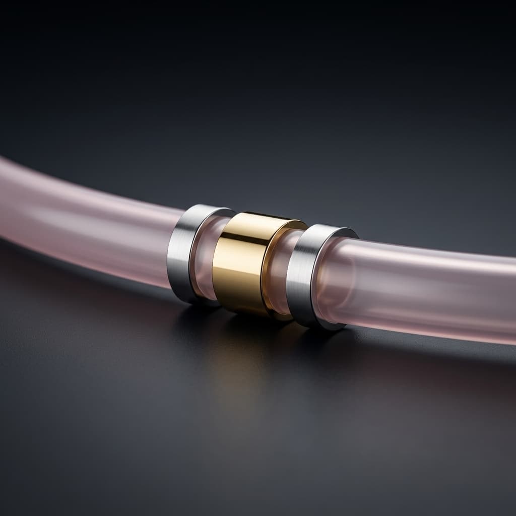
Catheter Marker Band Assembly: Swaging vs. Bonding for Radiopacity
A practical engineering guide to integrating radiopaque marker bands into reinforced catheter shafts. We compare swaging and thermal bonding techniques, dimensional tolerances, and inspection criteria.
Precise positioning under fluoroscopy is non-negotiable for cardiovascular and neurovascular catheters. Radiopaque marker bands—usually machined from Platinum-Iridium (Pt/Ir) or Gold—give physicians that critical visibility.
[!TIP] Key Takeaways for Buyers
- Swaging provides high mechanical retention without heat, but can increase the crossing profile unless the polymer is centerless ground first.
- Reflow Encapsulation can create a flush, atraumatic outer surface by melting the jacket over the band, but requires precise thermal profiling.
- Quality control should define applicable ISO 10555 pull-testing criteria and optical measurement requirements for placement accuracy (
±0.005"). - Gold is softer and easier to swage, but Pt/Ir provides superior radiopacity and structural integrity.
But getting these metallic bands securely attached to a polymer shaft without compromising the catheter profile is a demanding manufacturing challenge. Marker retention is a critical-to-quality requirement. Choosing between swaging (crimping) and thermal bonding (reflow encapsulation) directly impacts your device's safety profile and tracking performance.
1. Swaging (Mechanical Crimping)
Swaging involves mechanically compressing the metallic band directly onto the underlying catheter structure using specialized radial crimping equipment (e.g., 8-die or 12-die swaging machines).
When to Specify Swaging
Swaging is typically utilized on the outermost jacket of the catheter or on unjacketed distal tips where thermal reflow is impossible.
Advantages:
- High Retention Force: When executed correctly, swaging drives the metal into the polymer, creating an immediate, strong mechanical lock.
- No Heat Required: Ideal for temperature-sensitive components, delicate inner liners, or shafts with highly heat-sensitive sensor wiring.
- Speed & Yield: The process is highly repeatable, easily automated, and fast in a production environment.
Challenges & Limitations:
- Profile Increase: If not recessed properly, the swaged band increases the local outer diameter (OD) of the catheter. This creates a "bump" that hinders trackability and can catch on introducer sheaths.
- Substrate Damage: Over-crimping can crush the underlying PTFE liner or damage the braid/coil reinforcement layer, compromising lumen integrity.
- Spring-back: Certain metal alloys experience "spring-back" after swaging, slightly reducing the retention force over time.
Engineering Tip: To achieve a flush OD with swaging, specify a centerless grinding operation on the polymer jacket to create a recessed pocket equal to the band's wall thickness (typically 0.001" to 0.002") prior to swaging.
2. Thermal Bonding / Reflow Encapsulation
In this method, the marker band is placed over the inner liner or reinforcement layer, and an outer polymer jacket is reflowed (melted) completely over and around the band using FEP heat shrink tubing and a thermal source.
When to Specify Reflow Encapsulation
Reflow is the gold standard for neurovascular microcatheters, guiding catheters, and any device where crossing profile and atraumatic navigation are the highest priorities.
Advantages:
- Seamless Outer Profile: The polymer encapsulates the band to create a smooth, flush outer surface target.
- Encapsulation Barrier: Encapsulation helps reduce dislodgement risk in tortuous vessels and covers metallic edges that could otherwise damage the intima of the blood vessel.
- Integrated Manufacturing: The band can be integrated during the same reflow step that laminates the braid/coil and jacket, streamlining production.
Challenges & Limitations:
- Thermal Management: Requires precise temperature control to ensure the polymer flows evenly around the metal band without degrading. Metals heat up faster than polymers, which can cause localized burning if the thermal profile isn't optimized.
- Air Entrapment: If the polymer does not wet out evenly around the band's edges, micro-bubbles can form adjacent to the band, creating weak points where the jacket might tear.
- Minimum Wall Constraints: Encapsulating a band requires sufficient wall thickness in the outer jacket (at least
0.0015" - 0.002"clearance over the band) to prevent the band from bursting through the polymer.
3. Best Practices for OEM Manufacturing
When working with an OEM for marker band assembly, ensure the RFQ addresses the following Critical-to-Quality (CTQ) specifications:
| Feature | Design Consideration | OEM Inspection Requirement |
|---|---|---|
| Placement Accuracy | Distance from the distal tip to the leading edge of the band. | High-resolution optical comparators (e.g., Keyence systems) measuring to ±0.005". |
| Retention Force | Force required to dislodge the band longitudinally. | Destructive pull-testing utilizing Instron equipment to verify against ISO 10555 standards. |
| Concentricity & OD | The band must not distort the lumen or create a high spot. | Laser micrometers to measure the shaft OD across the band location. |
| Material Ratio | Typically 90% Platinum / 10% Iridium. | Material certs and lot traceability records linked to the specific DHR. |
Source Your Marker Band Assembly Confidently
Securing radiopaque markers is a high-risk CTQ process. Our team specializes in both precision radial swaging and flush thermal encapsulation for complex braided and coil-reinforced shafts. Send your drawings or RFQ to [email protected] for an engineering review.
Frequently Asked Questions (FAQ)
What is the minimum wall thickness required to encapsulate a marker band?
As a practical starting point, allow at least 0.0015" clearance over the marker band OD so the polymer jacket can flow over it without exposing the metal or creating micro-tears during flex.
Should I choose Gold or Platinum-Iridium?
Gold is highly radiopaque and much softer, making it easier to swage without damaging the underlying shaft. However, Pt/Ir (90/10) offers superior mechanical strength and biocompatibility, making it the preferred choice for long-term implants or highly stressed distal tips.
Author: Jonny - Senior Catheter R&D Specialist. Jonny leads complex shaft integration projects and focuses on DFM for structural heart and neurovascular delivery systems.
Author

Categories
More Posts
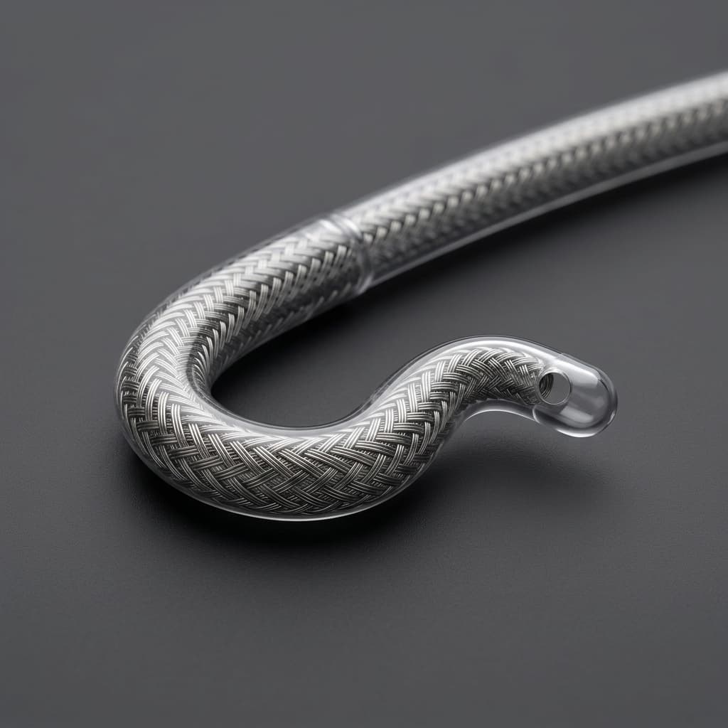
FDA Class I Recall (July 2026): Mitigating Distal Tip Detachment in Delivery Catheters
The recent Class I recall of a major delivery catheter system over distal tip detachment highlights critical risks in inner shaft assembly and transition zone bonding. Learn how buyers and OEM engineers can audit suppliers to prevent this manufacturing defect.
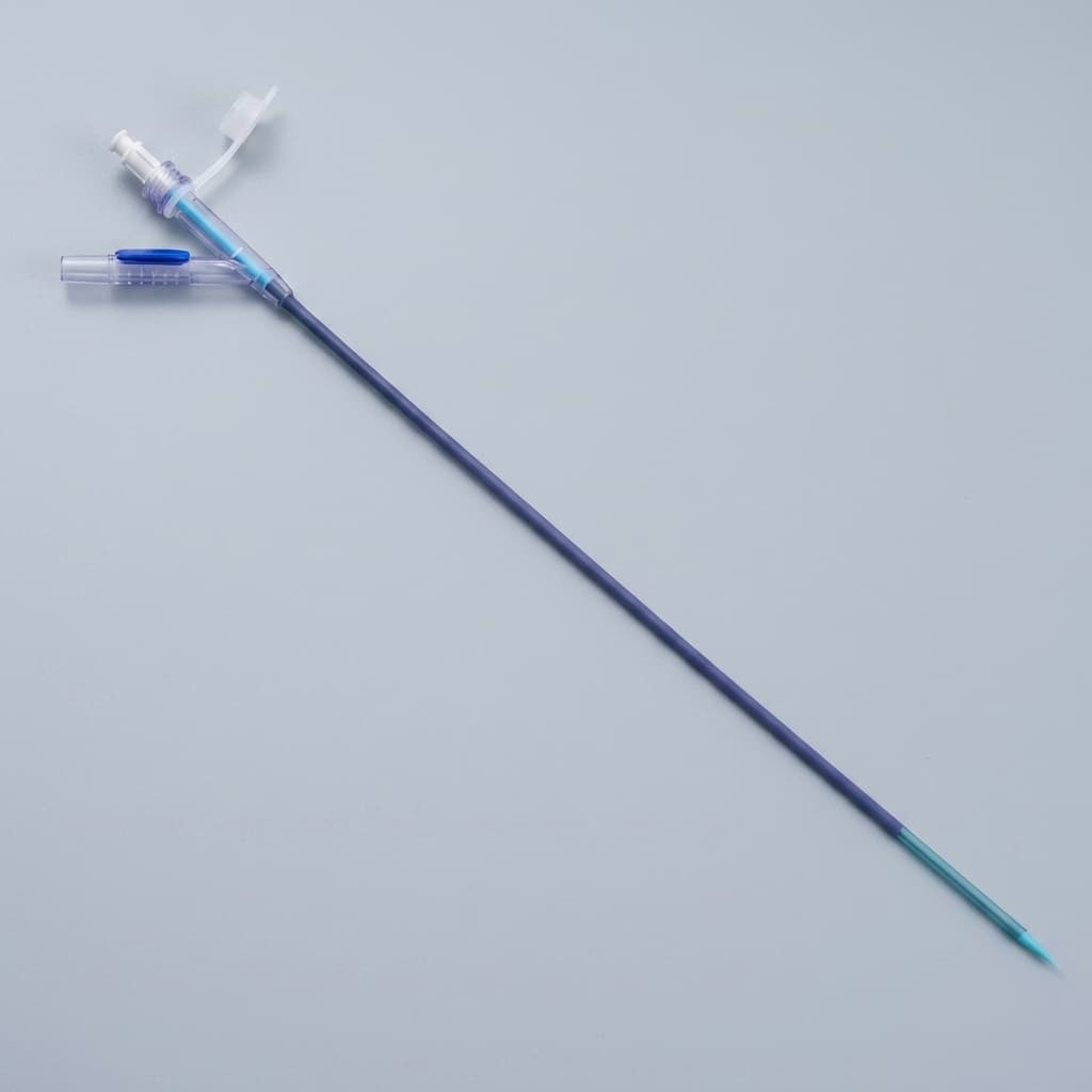
Buyer Guide: How to RFQ Braided & Coil Reinforced Catheter Shafts
A practical engineering and sourcing checklist for medical device teams evaluating catheter shaft OEM partners. Includes specific CTQ tolerance guides and material selection matrices.
Braided vs. Coil Reinforced Catheters: Choosing the Right Shaft Architecture
A deep dive into when to specify a braided catheter shaft versus a coil reinforced catheter for neurovascular, cardiovascular, and structural heart applications. Includes material data and PPI calculations.