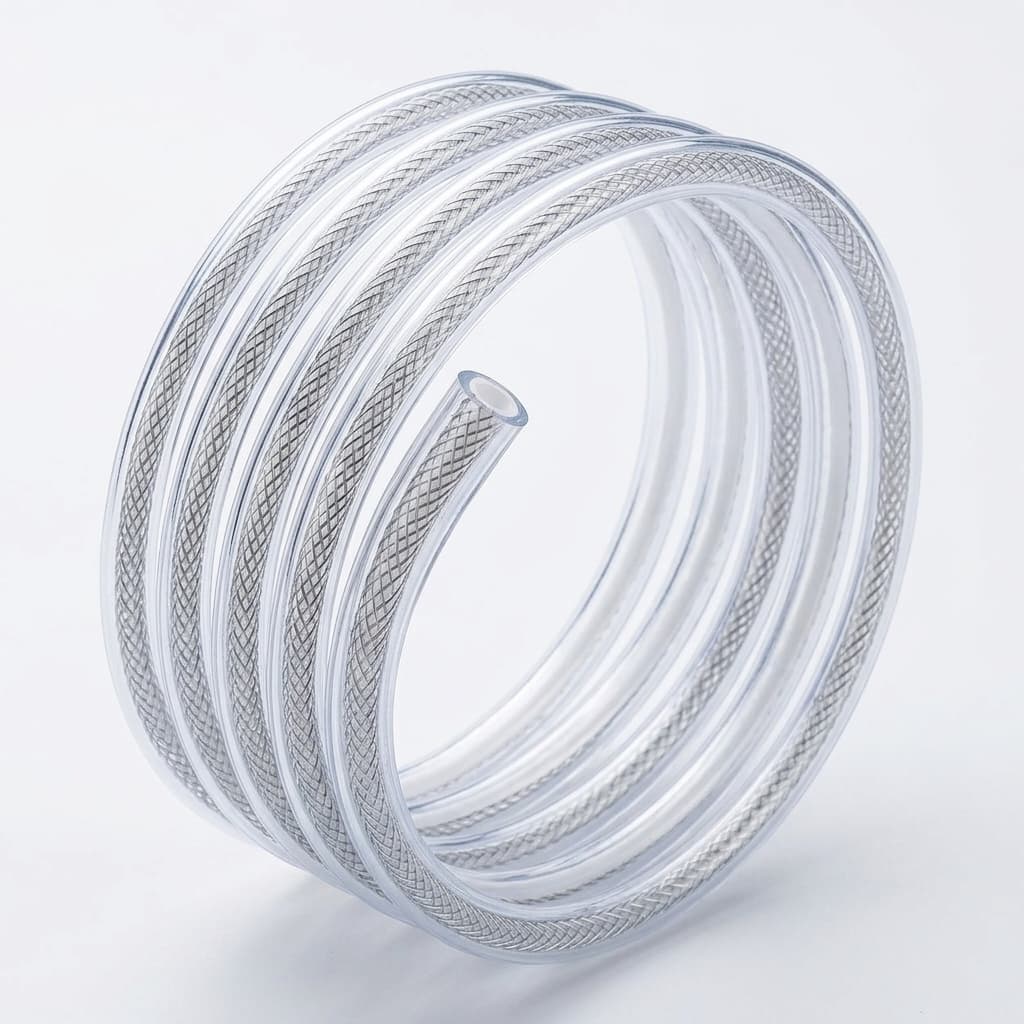
PTFE Liner Reflow: How to Avoid Delamination and Pinholes in Catheter Shafts
A technical review of the catheter reflow lamination process, focusing on mitigating common defects like PTFE liner delamination, pinholes, and uneven jacket flow.
Moving a PTFE-lined catheter from benchtop prototype to pilot production usually exposes hidden reflow defects. The thermal reflow (lamination) process is unforgiving—it demands precise control over heat shrink tension, temperature profiles, polymer melt indexes, and cooling rates. If any of these are off, you'll see it on the inspection line.
[!TIP] Key Takeaways for Buyers
- Delamination is often caused by degraded PTFE etching (sensitive to UV/humidity) or incorrect melt flow index (MFI) temperatures.
- Pinholes & Voids typically result from hygroscopic polymers (Nylon/Pebax) absorbing ambient moisture before lamination. Strict desiccant drying is mandatory.
- Lumen Distortion (Neck Down) is prevented by matching the mandrel OD to the liner ID within an ultra-tight tolerance of
< 0.0005". - Always audit an OEM's thermal profiling and material storage protocols to prevent pilot-stage failures.
When a medical device team shifts from benchtop prototyping to pilot production, previously hidden defects often emerge. Here, we outline the most common PTFE liner reflow defects, their thermodynamic root causes, and how OEM manufacturing partners mitigate them.
1. PTFE Liner Delamination (Peeling)
The Problem: The outer polymer jacket (e.g., Pebax, Nylon, or Polyurethane) fails to adhere completely to the inner PTFE liner, creating a weak mechanical bond. Under severe bending, torque testing, or in-vivo tracking, the layers separate. This separation severely degrades torque response and can cause the lumen to collapse.
Root Causes & Solutions:
- Inadequate or Degraded Etching: PTFE is naturally non-stick (hydrophobic with extremely low surface energy). To achieve a strong mechanical bond, the outer surface must be chemically etched (typically using a sodium-naphthalene or sodium-ammonia solution) to strip fluorine atoms and create a carbonaceous layer.
- Mitigation: Etched PTFE degrades rapidly when exposed to UV light, humidity, or extreme heat. OEMs must implement strict inventory control, use black UV-protective bags, and enforce a strict shelf-life (often < 6 months).
- Insufficient Melt Flow Penetration: If the outer jacket does not reach its exact Melt Flow Index (MFI) temperature, the polymer will not fully wet out and penetrate the etched pores of the PTFE.
- Mitigation: Conduct precise thermal profiling of the reflow oven or hot air nozzle. The thermal setpoint must account for the specific durometer of the jacket—for instance, Pebax 35D requires a significantly lower reflow temperature profile than Pebax 72D.
2. Pinholes and "Fish Eyes" (Voids)
The Problem: Microscopic voids or bubbles appear in the outer jacket after reflow. These voids create a direct path for fluids to leak, reduce the dielectric strength of EP catheters, and act as stress-concentration points where the catheter may snap.
Root Causes & Solutions:
- Moisture Absorption (Hydrolysis): Polymers like Nylon 12 and Pebax are highly hygroscopic. If they absorb ambient moisture prior to reflow, the water flashes to steam during the high-temperature lamination process, creating bubbles in the melt.
- Mitigation: Implement strict desiccant drying protocols. All jacket extrusions should be baked in a vacuum or desiccant oven (e.g., 60°C for 4 hours) and stored in humidity-controlled environments (RH < 20%) immediately prior to lamination.
- Trapped Air: If the FEP heat shrink tubing recovers unevenly, it can trap ambient air against the reinforcement layer (braid or coil).
- Mitigation: Ensure directional heating (e.g., passing the shaft through a heat nozzle from proximal to distal end at a controlled rate). This forces the heat shrink to recover sequentially, acting as a squeegee that pushes air out ahead of the melt front.
3. "Neck Down", Wrinkling, or Lumen Distortion
The Problem: The inner diameter (ID) of the PTFE liner compresses, ripples, or becomes ovalized. This violates the strict dimensional tolerances required for guide wires, therapeutic devices, or microcatheters to pass smoothly through the lumen.
Root Causes & Solutions:
- Improper Mandrel Sizing: The mandrel (typically Silver-Plated Copper (SPC) or solid 304V stainless steel) provides the internal support during reflow. If the mandrel OD does not closely match the PTFE liner's ID, the liner can buckle and wrinkle under the compressive force exerted by the recovering heat shrink.
- Mitigation: Specify precision tolerances. The gap between the mandrel OD and the liner ID should ideally be less than
0.0005". SPC mandrels are often preferred because they can be easily stretched for removal post-reflow.
- Mitigation: Specify precision tolerances. The gap between the mandrel OD and the liner ID should ideally be less than
- Excessive Heat Shrink Recovery Force: High-ratio FEP heat shrink (e.g., 1.6:1 or 2:1) can exert too much compressive force, crushing the internal structure, especially over low-durometer jacket segments or unreinforced transition zones.
- Mitigation: Select FEP tubing with the lowest possible recovery ratio necessary for the job, and optimize the wall thickness of the FEP.
4. OEM Process Qualification Checklist
When auditing an OEM partner for your catheter braiding and reflow projects, ask to review their validation data. A reliable partner won't just assemble components; they will engineer the process to prevent defects.
Ask your OEM:
- What is your shelf-life and storage protocol for etched PTFE?
- How do you verify the moisture content of hygroscopic jacket extrusions before reflow?
- Do you use automated, PLC-controlled reflow equipment (e.g., traverse systems) to ensure repeatable directional heating?
- How do you measure ID/OD concentricity post-reflow?
Need assistance troubleshooting a reflow issue, establishing thermal profiles, or looking for a reliable manufacturing partner? Contact us at [email protected] to discuss your next catheter build.
Frequently Asked Questions (FAQ)
What is the ideal reflow temperature for Pebax 35D?
The exact thermal profile depends on the heat shrink ratio and wall thickness, but Pebax 35D typically requires a reflow melt temperature between 140°C and 160°C. Exceeding this can cause polymer degradation or thermal damage to the PTFE liner.
Why do we use Silver-Plated Copper (SPC) mandrels?
SPC mandrels provide excellent dimensional stability during reflow. Crucially, copper can be elongated (stretched) after the reflow process. This stretching locally reduces the mandrel's outer diameter, allowing it to easily slip out of the tight catheter shaft without damaging the inner lumen.
Author: Liam - Senior Process Engineer. Liam specializes in thermodynamic polymer flow, multi-lumen extrusion, and advanced catheter reflow lamination.
Author

Categories
More Posts
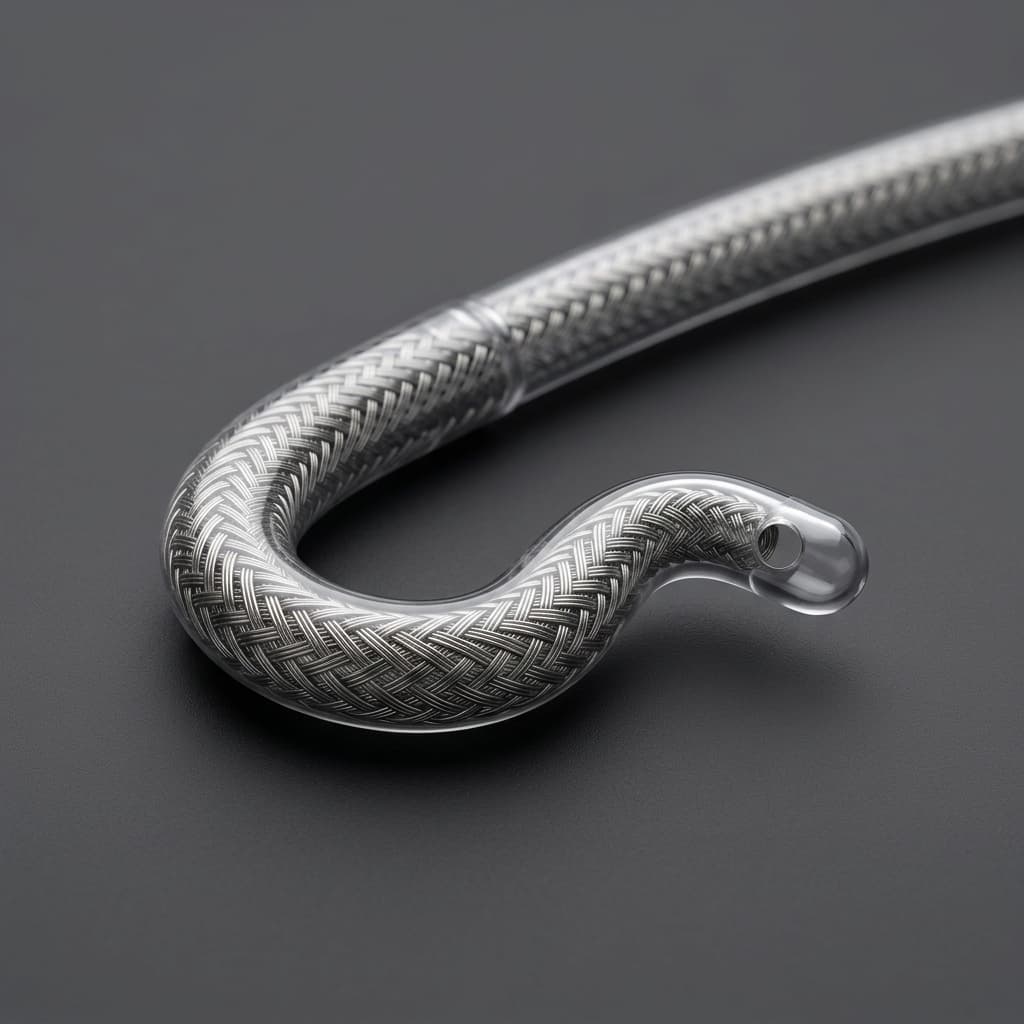
FDA Early Alert: Abiomed/Oscor Large-Bore Sheath Leakage and Hub Bonding Risks
The June 2026 FDA Early Alert regarding Abiomed and Oscor 14Fr/23Fr introducer sheaths reveals critical hub bonding and splittable score line vulnerabilities in large-bore catheter manufacturing.
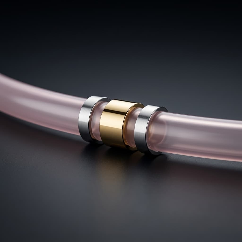
Catheter Marker Band Assembly: Swaging vs. Bonding for Radiopacity
A practical engineering guide to integrating radiopaque marker bands into reinforced catheter shafts. We compare swaging and thermal bonding techniques, dimensional tolerances, and inspection criteria.
Braided vs. Coil Reinforced Catheters: Choosing the Right Shaft Architecture
A deep dive into when to specify a braided catheter shaft versus a coil reinforced catheter for neurovascular, cardiovascular, and structural heart applications. Includes material data and PPI calculations.