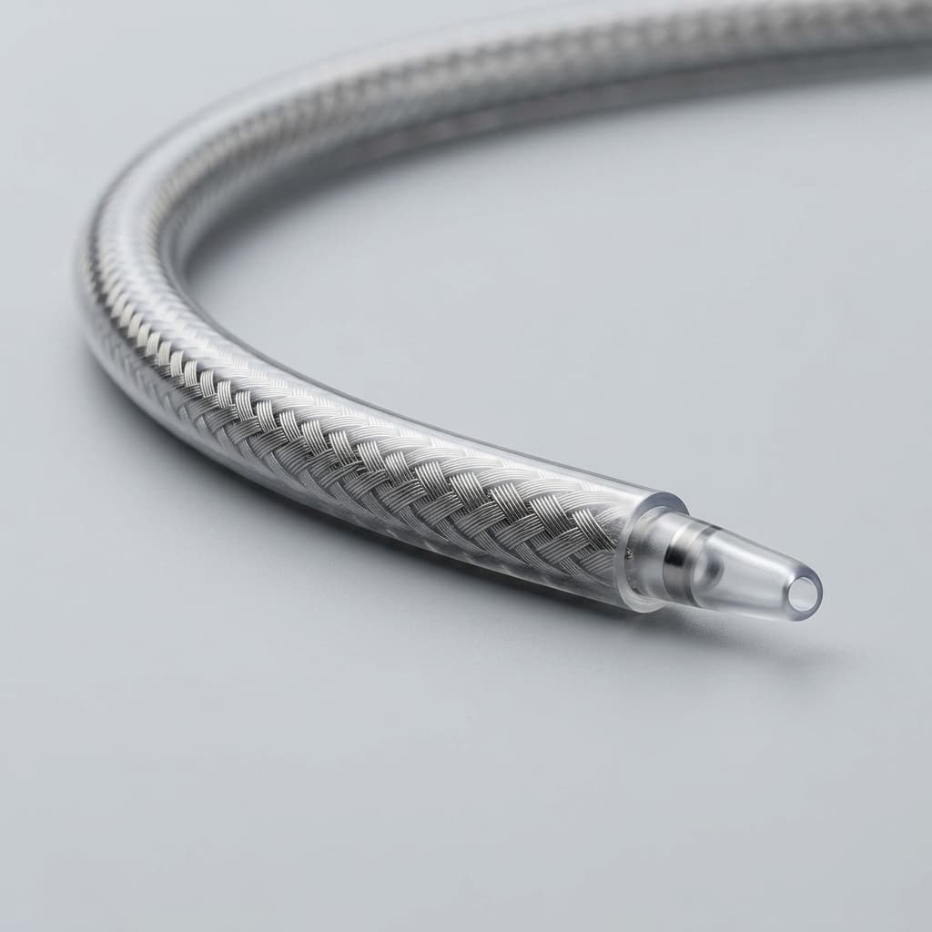
Variable Pitch vs. Multi-Segment Braiding: Optimizing Catheter Flexibility and Cost
Compare variable pitch braiding vs multi-segment catheter shafts for flexibility, kink risk, yield, cost, and OEM RFQ decisions. Request a DFM review.
When designing minimally invasive delivery systems, structural heart catheters, or neurovascular microcatheters, engineers often compare variable pitch braiding vs. multi-segment braiding to solve a universal paradox: the proximal end of the catheter must be stiff enough to provide 1:1 torque response and pushability from the physician's hand, while the distal end must be highly flexible to track through tortuous, fragile vasculature without causing trauma.
For decades, the industry standard for achieving this proximal-to-distal flexibility gradient was the multi-segment catheter shaft. This method involves manufacturing several distinct braided sections, each with a different flexibility profile, and manually bonding or thermally fusing them together end-to-end. While functional, this approach introduces significant points of failure, manufacturing bottlenecks, and high scrap rates.
Enter continuous variable pitch braiding (also known as continuous pitch variation). Modern servo-controlled braiding equipment allows manufacturers to dynamically alter the braid density—measured in Picks Per Inch (PPI)—along the length of a single, continuous wire matrix. This eliminates the need for bonded joints, fundamentally transforming both the mechanical performance of the catheter and the economics of large-scale production.
This comprehensive guide explores the physics, manufacturing realities, and procurement implications of variable pitch braiding versus traditional multi-segment assembly, providing R&D engineers and supply chain professionals with the actionable data needed to optimize their next catheter program.
Scope note, published July 20, 2026: This guide is written for global catheter OEM engineering, sourcing, and early DFM discussions. It does not replace device-specific verification, clinical risk analysis, tensile/kink/torque testing, biocompatibility review, or regulatory submissions. Treat the PPI ranges, yield ranges, and cost examples below as RFQ planning assumptions to validate against your shaft length, wire size, carrier count, polymer stack, reflow equipment, inspection plan, and supplier process capability.
If you are preparing supplier inputs now, pair this comparison with the catheter shaft RFQ checklist and then send drawings through the contact / RFQ form for a DFM review.
The Physics of Braid Density (PPI) and Performance
To understand why variable pitch matters, we must first look at the relationship between braid density and catheter mechanics. Braid density is defined by Picks Per Inch (PPI), which refers to the number of wire crossovers (or "picks") along one linear inch of the catheter shaft.
The PPI directly correlates with the braid angle—the angle at which the wire crosses the longitudinal axis of the catheter. A higher PPI results in a higher braid angle (closer to 90 degrees), while a lower PPI results in a lower, flatter angle.
- High PPI (e.g., 60-80 PPI): Generates a dense, tight mesh. This structure vastly increases radial strength, burst pressure, hoop strength, and 1:1 torque transmission. However, the high density restricts longitudinal bending, making the shaft stiff and rigid. This is ideal for the proximal shaft, which remains largely in straight anatomy (like the femoral artery) and requires pushing force.
- Low PPI (e.g., 20-30 PPI): Creates a loose, elongated mesh. Radial strength decreases, but longitudinal flexibility increases dramatically. This configuration allows the catheter to bend through acute angles and tortuous neurovascular or coronary pathways without exerting excessive outward force on delicate vessel walls.
In a clinical setting, a physician requires the proximal performance of a high-PPI braid and the distal performance of a low-PPI braid. The engineering challenge lies entirely in how to connect these two distinct zones.
For teams still choosing the reinforcement architecture, review the broader braided vs. coil reinforced catheter shaft comparison before freezing the braid program.
The Traditional Method: Multi-Segment Braiding and the "Hinge" Problem
Historically, manufacturers solved the flexibility requirement by producing discrete sub-assemblies. A typical structural heart delivery system might consist of a proximal section (braided 304V stainless steel at 60 PPI), a mid-section (40 PPI), and a distal section (20 PPI or even a transition to an unbraided polymer coil).
These distinct tubular segments are mated together using thermal butt-welds, reflowed polymer overlaps, or adhesive lap joints. While this technique does create a graduated flexibility profile, it introduces significant electromechanical and manufacturing liabilities.
The Disadvantages of Multi-Segment Joints
- Stress Concentrations and Kinking: A bonded joint between two materials of differing flexural moduli acts as a pivot point, commonly referred to as a "hinge." When the catheter navigates a tight radius in the vasculature, the bending force concentrates abruptly at the joint rather than distributing evenly along a curve. This hinging effect is the primary cause of shaft kinking and lumen collapse in multi-segment devices.
- Delamination and Tensile Failure: The bond between two distinct braided sections is inherently weaker than the continuous braided wire itself. Under extreme tension (such as when withdrawing a device that has become lodged), these butt-joints can suffer cohesive or adhesive failure, leading to the catastrophic clinical event of distal tip detachment.
- Compromised Lumen Dimensions: To reinforce a butt-joint, engineers often add an extra layer of polymer over-jacket or a short segment of metallic support tubing (a marker band or hypotube sleeve). This adds bulk to the outer diameter (OD) and can compromise the inner diameter (ID), violating the strict dimensional tolerances required for passing guide wires or implants.
- High Scrap Rates: The manual assembly and thermal reflow of multiple tiny joints under a microscope is a highly operator-dependent process. Yield rates for multi-segment assemblies are notoriously low, as misalignments of even 0.001" at the joint can cause the shaft to fail concentricity and wall-thickness inspections.
Continuous Variable Pitch Braiding: A Paradigm Shift
Continuous variable pitch braiding eliminates the need for physical joints. Utilizing advanced PLC (Programmable Logic Controller) driven braiding machines, the manufacturer can program the machine's take-off speed to accelerate or decelerate smoothly while the carriers maintain a constant rotational speed.
Because the wires never stop traversing, the resulting braid transitions seamlessly from a high PPI to a low PPI. The change can be engineered as a gradual, linear shift over several inches (ideal for smooth tracking), or as an abrupt step-down over a millimeter (if a sudden change in stiffness is required).
Key Advantages of Continuous Pitch Variation
- Absolute Structural Integrity: Because the metallic reinforcement (whether 304V Stainless Steel, Nitinol, or Tungsten) is a single, uninterrupted matrix from the proximal hub to the distal tip, tensile strength is maximized. The risk of the shaft snapping at a joint is eliminated.
- Optimal Torque Transfer: A continuous wire structure allows torsional forces applied at the handle to travel seamlessly down the shaft without being absorbed or dampened by a polymeric bond joint. This results in superior, highly predictable 1:1 torque response.
- Smooth Flexibility Gradients (No Hinging): The flexural modulus of the shaft changes continuously rather than discretely. When the catheter bends, it forms a natural, sweeping arc, dramatically improving kink resistance and trackability through complex anatomies.
- Reduced Profile: Without the need for overlap joints or reinforcing sleeves, the wall thickness of the catheter can be minimized, allowing for a larger ID and a smaller OD—a critical metric in modern interventional cardiology and neurology.
Performance and Manufacturing Comparison
To clearly quantify the differences for procurement teams and design engineers, we have compiled the following structural and economic comparison between the two manufacturing methodologies.
| Feature / Metric | Multi-Segment Bonding | Continuous Variable Pitch Braiding | Clinical / Manufacturing Impact |
|---|---|---|---|
| Braid Continuity | Interrupted (cut and bonded) | 100% Continuous | Continuous wire prevents tensile failure and tip detachment during withdrawal. |
| Kink Resistance (Transition) | Poor (Hinge point at joint) | Excellent (Smooth arc) | Variable pitch prevents lumen collapse in tight anatomical radii. |
| Torque Transmission | Dampened at polymer joints | Instantaneous (1:1 response) | Superior physician control for steering and device deployment. |
| Outer Profile (OD) | Often requires bulky joint overlaps | Minimal, consistent wall thickness | Allows for smaller French sizes and access to more distal vasculature. |
| Yield / Scrap Rate | High scrap (operator-dependent joints) | Low scrap (automated, repeatable) | Dramatically reduces unit cost at scale by eliminating manual assembly errors. |
| Labor Content per Unit | High (manual layout and reflow) | Low (machine-driven) | Protects supply chain against labor shortages and reduces COGS. |
| Initial NRE & Tooling | Moderate | High (programming & profiling) | Variable pitch requires more upfront engineering but pays off rapidly in production. |
| Durometer Matching | Easy (match polymer to segment) | Complex (requires variable extrusion/reflow) | OEM must expertly reflow multiple Pebax durometers over the continuous braid. |
Material Combinations and Polymeric Reflow
Implementing variable pitch braiding is only half the engineering equation. The underlying continuous braid must be paired with appropriate inner liners and outer jackets.
Wire Selection
The choice of wire material deeply affects the variable pitch profile:
- 304V / 316L Stainless Steel: The standard for high torque and pushability. Excellent for variable pitch profiles where proximal support is the primary requirement. Flat wire is often used over round wire to maintain a lower profile while maximizing surface coverage at the lower PPI distal end.
- Nitinol (NiTi): Utilized when extreme kink resistance and shape memory are required. Nitinol allows the distal low-PPI sections to endure severe bending without undergoing plastic deformation.
The Challenge of Variable Durometer Reflow
While the braid is continuous, the outer polymer jacket still needs to transition in flexibility. Engineers typically achieve this by sliding discrete segments of different polymer durometers (e.g., Pebax 72D proximally, transitioning through 55D, 40D, to a soft 35D distally) over the continuous braid.
During the thermal reflow process, these polymer segments melt together and flow into the interstices of the braid. Because the braid density is changing beneath the polymer, the OEM must precisely profile the reflow temperatures. A low-PPI distal section has larger gaps between wires, requiring careful control to prevent the low-durometer Pebax from penetrating too deeply and wrinkling the inner PTFE liner.
Always verify that your OEM has automated, traverse-style thermal reflow equipment to handle the complex thermodynamics of variable-pitch jacket lamination. If liner bonding, pinholes, or jacket flow are the main risks, use the PTFE liner reflow defect checklist during supplier review.
Procurement and Supply Chain Economics
For procurement teams and supply chain managers, the decision to migrate from a multi-segment design to a variable-pitch design is a classic Total Cost of Ownership (TCO) calculation.
While a contract manufacturer may charge higher Non-Recurring Engineering (NRE) fees to program the servo-braiders and validate the continuous reflow process, the long-term unit economics strongly favor variable pitch braiding.
By eliminating the manual labor required to cut, align, and thermally bond 2 to 4 distinct joints per catheter, cycle times typically fall and fewer transition zones need destructive validation. Furthermore, eliminating the joints removes a common source of failure during final inspection: concentricity failures, weak tensile tests, and pinholes at the weld.
As an RFQ planning example, assume a program needs 10,000 accepted shafts. At 15% scrap, a multi-segment process must start about 11,765 shafts; at 3% scrap, a validated continuous variable-pitch process must start about 10,309 shafts. That 1,456-start difference is where material, labor, inspection, and schedule savings show up. Do not quote those percentages as guaranteed supplier performance; ask each OEM for lot history, transition-zone inspection data, and tensile/kink test results for your exact design.
Engineer & Buyer OEM Checklist for Variable Pitch Sourcing
If you are specifying a variable pitch braided shaft in your next RFQ, use this checklist to audit potential contract manufacturing partners:
- Equipment Capability: Does the OEM use state-of-the-art, PLC-driven braiders (e.g., Steeger or Wardwell) capable of precise, linear PPI transitions without stopping the machine?
- Tolerance Controls: What is their stated tolerance for PPI transitions? (e.g., Can they hold a transition zone to within ±2mm of the specified length?)
- Wire Handling: Can they continuously braid flat wire, or are they limited to round wire? (Flat wire requires tension control systems to prevent twisting during the transition).
- Integrated Extrusion: Does the OEM extrude their own multi-durometer jackets in-house? (Vertical integration ensures the Pebax segments perfectly match the braid transitions).
- Reflow Automation: Do they use automated thermal nozzles or traverse ovens to reflow the jacket over the variable braid, ensuring consistent melt flow index (MFI) penetration?
- In-Line Inspection: Does the OEM utilize laser micrometers to verify the OD continuously across the transition zones?
For complex programs, include the transition map, target PPI by zone, accepted bend radius, tensile pull requirement, jacket durometer stack, inspection method, and annual volume in the first RFQ. Teams can use the contact / RFQ form when they need a manufacturability review before PO release.
Frequently Asked Questions (FAQ)
What is the maximum PPI change possible in a transition zone?
While highly dependent on the wire size and machine setup, a typical braiding machine can smoothly transition from 80 PPI down to 10 PPI. Abrupt step-changes can be programmed to occur within a few millimeters, or the transition can be stretched linearly over 10-20 centimeters.
Does continuous variable pitch braiding increase lead times?
During the initial prototyping and validation phases, programming and dialing in the variable pitch and corresponding reflow profiles can add 1-2 weeks compared to simple multi-segment builds. However, once validated for production, the lead time is actually reduced due to the elimination of manual bonding steps.
Can variable pitch be combined with variable wire counts?
Standard variable pitch changes the PPI (density), not the number of wires. To change the wire count (e.g., transitioning from a 16-wire proximal shaft to an 8-wire distal tip), a multi-segment approach or a highly specialized half-load transition is required. For most applications, varying the PPI on a continuous 16-wire braid achieves the required flexibility without dropping wires.
Is variable pitch braiding compatible with PTFE inner liners?
Yes, absolutely. The continuous braid is applied directly over the etched PTFE liner (supported by a metallic mandrel). The challenge lies in ensuring the outer polymer jacket reflows consistently through the changing braid gaps to mechanically lock onto the etched PTFE surface.
Conclusion and Next Steps
The shift from multi-segment catheter shafts to continuous variable pitch braiding represents a fundamental evolution in medical device manufacturing. By eliminating weak joints, engineers can push the boundaries of catheter trackability and torque response, while procurement teams benefit from automated, high-yield production.
If your current catheter design suffers from kinking at transition joints, distal tip detachment, or unacceptable scrap rates during assembly, it may be time to evaluate continuous braiding.
Ready to optimize your catheter design? Our engineering team specializes in translating multi-segment prototypes into high-yield, variable-pitch production shafts. Contact us to submit your specifications for a manufacturability review and RFQ.
Sources and References
Access checked July 20, 2026. These public capability pages support supplier capability context; design limits, yield, and cost assumptions must still be validated with device-specific supplier data.
- Arrotek. Medical device design and manufacturing capability page, https://arrotek.com/
- Steeger USA. Precision medical braiding equipment capability page, https://steegerusa.com/
- Medical Murray. Medical device and catheter development/manufacturing capability page, https://www.medicalmurray.com/
- Putnam Plastics. Medical plastic tubing and catheter manufacturing capability page, https://www.putnamplastics.com/
Author

Categories
More Posts
Nitinol vs. Stainless Steel 304V in Catheter Braiding: An OEM Sourcing and Cost-Benefit Guide
Compare Nitinol vs stainless steel 304V catheter braid wire for OEM sourcing, cost, kink risk, lead time, testing, and RFQ decisions. Request DFM input.
EtO Sterilization EPA Rules (2026): Impact on Catheter Polymer Selection and Sourcing
Use this 2026 EtO sterilization EPA rules guide to compare catheter polymer risks, radiation trade-offs, sourcing checks, and OEM review steps.
PTFE Liner Reflow: How to Avoid Delamination and Pinholes in Catheter Shafts
A technical review of the catheter reflow lamination process, focusing on mitigating common defects like PTFE liner delamination, pinholes, and uneven jacket flow.